The Fraser Pit
2012 'Smoke'. 560hp 3S-GTE. - Hello, Strangers!
Hello, Strangers!
Well, apologies for the radio silence on updates. Get comfortable.
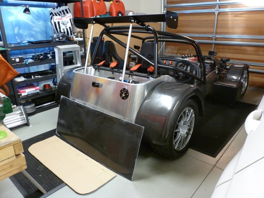
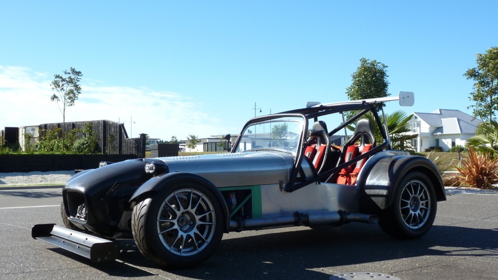
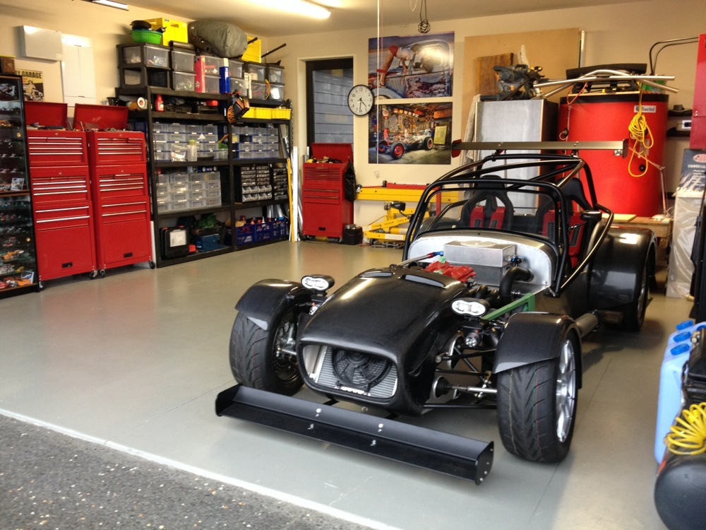
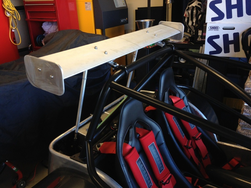
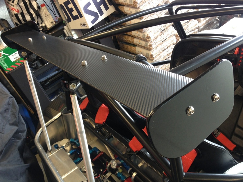
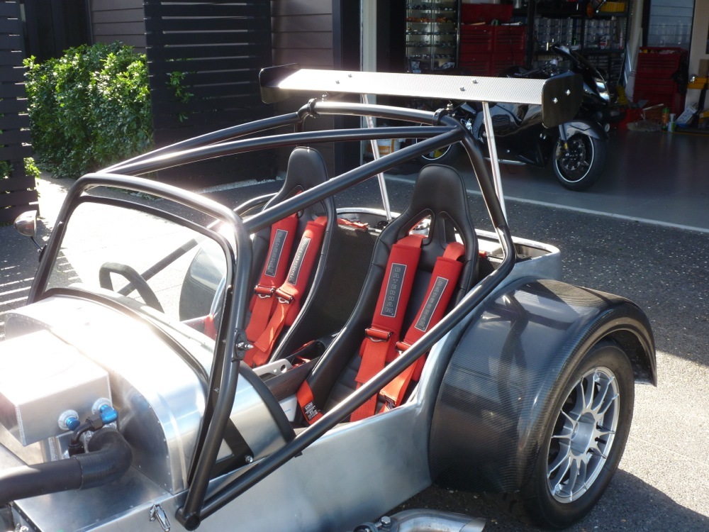
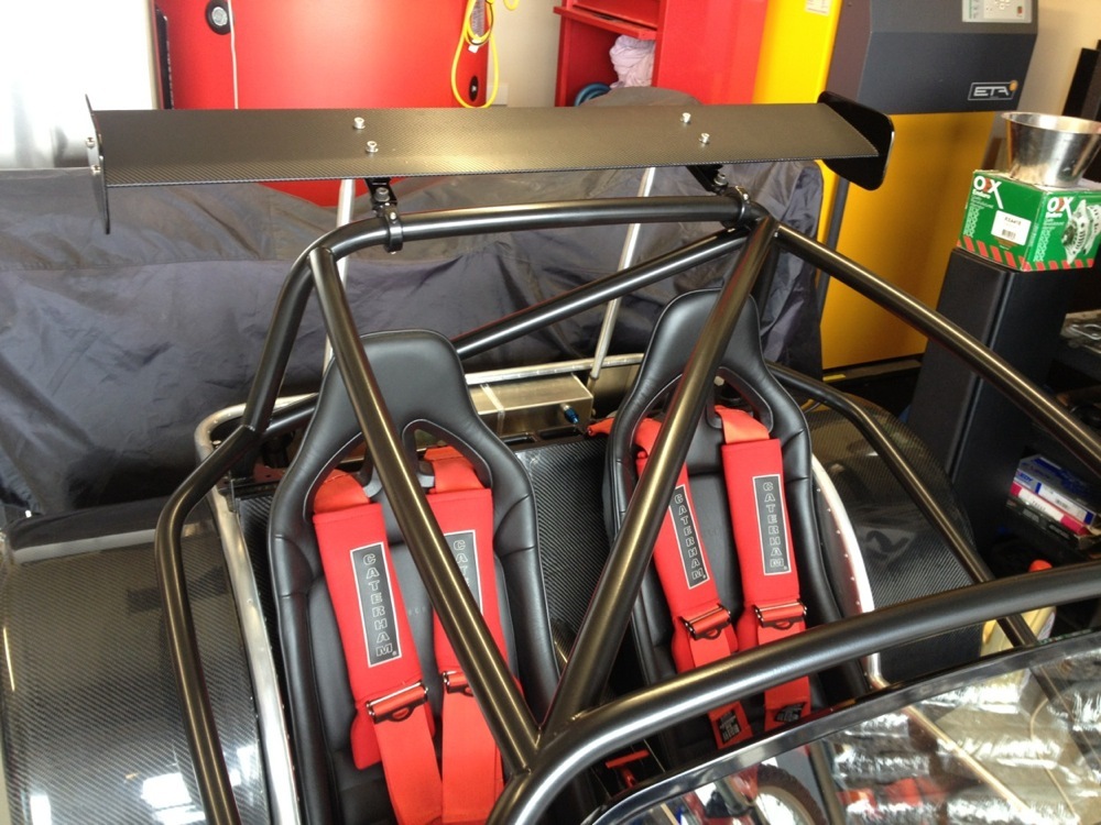
REAR WING
A pair of 1.5” PIAA spot-light roll-bar mounts and a pair of sprint-car front suspension struts along with a pair of very poorly (home) made wing cradles resulted in a moderately secure rear wing. I cut the end plates down in size to match the car’s tiny proportions then covered the wing in CF vinyl. Relatively pleased with the end result. Very hard to get the proportions/height/attack angle right when 7s don’t usually carry such hideous appendages.
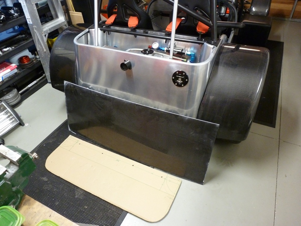
GLOVE BOX AND 'BOOT' LID
The last piece of fibre glass on the car has now been removed with the arrival of the CF glove-box. Everything is now either aluminum of CF. Nose cone with aero whiskers, front and rear guards, dash, seat bulkhead, glove-box and boot lid. I have a large panel of CF that I will cut down for the 2-piece boot lid. Probably have to fab a thin ali frame for the underside to give it a bit of strength. Looking around for a long piano-hinge to join the two pieces. Should look okay. Will also need to cut out slots for the wing struts. Carefully. I hate cutting into CF. Easier after 4 beers.
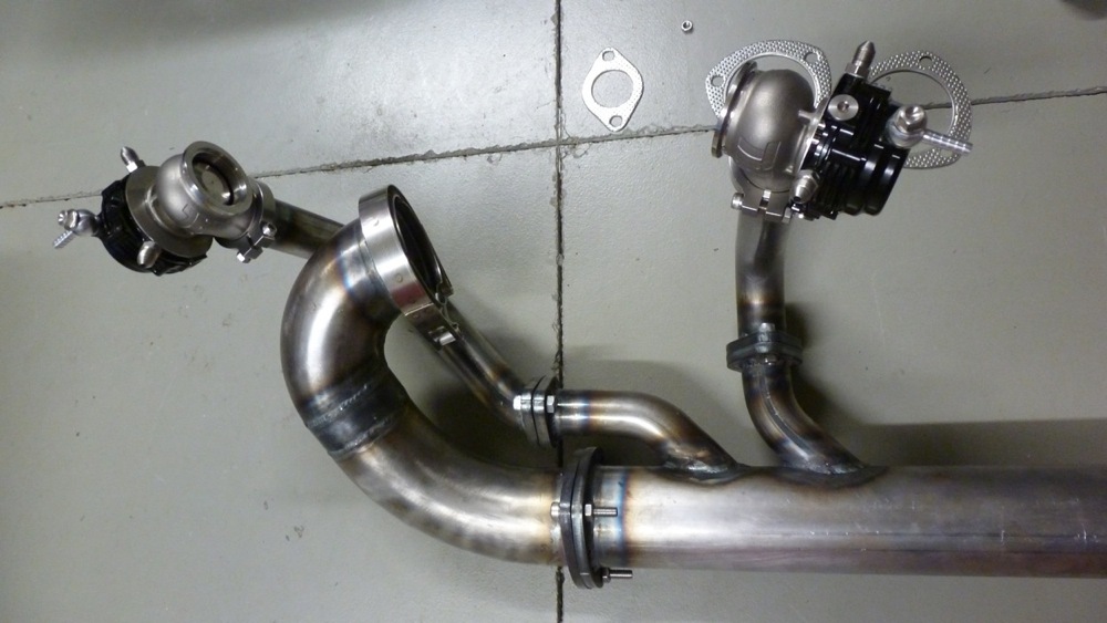
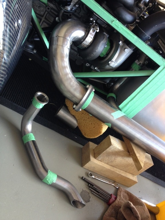
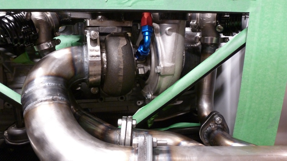
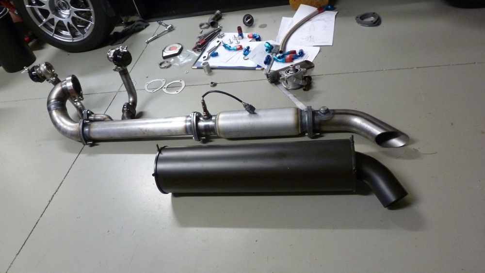
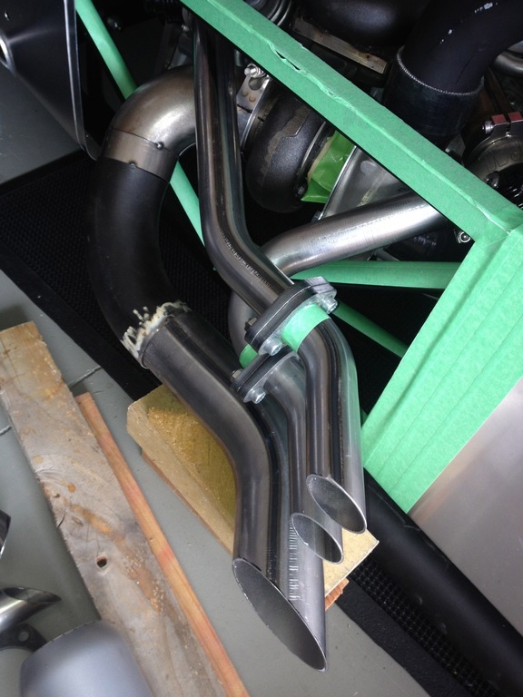
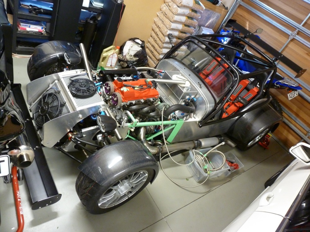
EXHAUST SYSTEM
After much swearing and throwing around of ruined pieces of steel tube, I managed to come up with a design for the waste gate dump tubes. A few trips between home and the welder’s shop, me producing ghastly tacks, them abusing my welding skills and seam welding things together in stages, home to test the fit, back to the shop etc. Came out pretty well in the end. Fairly discrete where they plug into the main 3” exhaust. Same can’t be said for the optional straight exhaust dump pipe and waste gate dump pipes. Just made these up for sh1ts and giggles post-certification. I can see a pending YouTube video of the engine running...HPC silver for all pipework most likely.
MOTEC M130 MAGNESIUM ECU WITH GPR SOFTWARE
Right. ECU upgrade. Again. 3rd ECU and the engine has not turned over once. After talking to a number of tuners about the project, I decided to upgrade to full Drive By Wire (Electronic Throttle, or E-Throttle). The DTA S80 did not support DBW so back it went to MSEL and an order was placed for the latest Motec M130 Magnesium with GPR software and Motec CAN-Bus Lambda kit. What a piece of kit. I am working through the very extensive Motec Webinars learing how to program and tune this beast. Very, very impressive piece of kit, must say. Have not blown it up (yet) so I must be doing something right (or just plain dumb luck...). With the arrival of the M130, my GFB Boost Controller and NGK Lambda Kit were both made redundant as the Motec controls everything now. Managed to sell these to a friend doing a home-built 7.
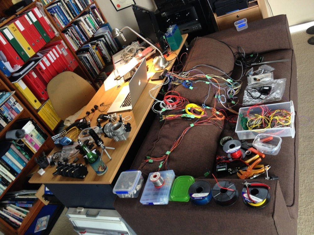
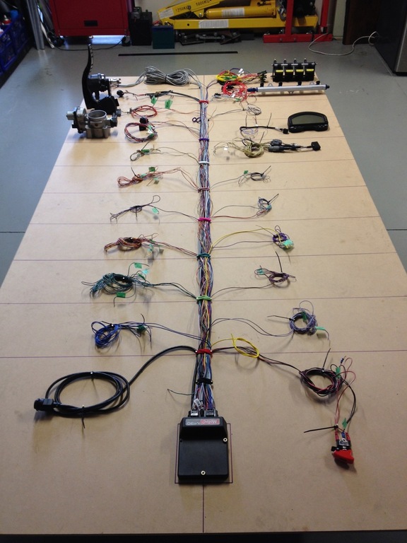
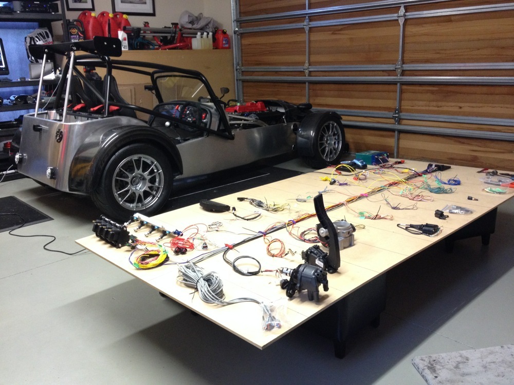
ECU WIRING LOOM
Wiring. Joy of joys. I love wiring. Not really. I took the original Link ECU loom, having modified it to suit the DTA ECU, and tore it apart again for the Motec configuration. Managed to produce a massive bird’s nest in the study, so mounted everything on a piece of MDF in the garage. Much better. I am adding ancillaries slowly and everything seems to be working okay. The coils and injectors are all plugged in, the AIM digital dash is talking to the ECU via CAN, the Lambda seems to be good, the crank and cam sensors are working (more on the crank sensor in a bit), and the traction control loom and sensors are also talking to the ECU. Working through the vast array of optional sensors/controllers that can be used and pairing these up with the variety of inputs/outputs on the Motec. Will place an order for sensors this week.
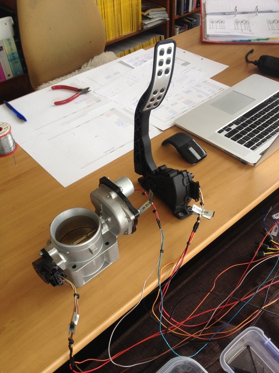
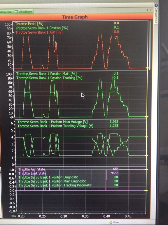
ELECTRONIC THROTTLE (DBW)
Right. This one is very cool. I sourced a new Falcon FG E-throttle pedal and Falcon BA E-throttle body from EBay Ausssie. Lots of phone calls and a lazy 20 over the service counter at the local Ford Stealership produced wiring diagrams. A day cutting myself to bits wandering around the wrecking yards produced a handful of OEM plugs to fit the pedal and throttle body. Several days of messing around with the programming of the ECU saw the throttle body operating perfectly. Very tricky to set up with the PID controller. I won’t bore you with details, but setting up the proportional, integral and differential gain, the various electronic clamps and offset and scale adjustments to prevent the throttle body jumping around like a landed fish was highly entertaining. Both the pedal and body have two TPS sensors that need to be set up and tuned. I set up two half-bridge outputs from the ECU to act as a full-bridge output to drive the servo motor on the throttle body. Tricky. Done. Sorted.
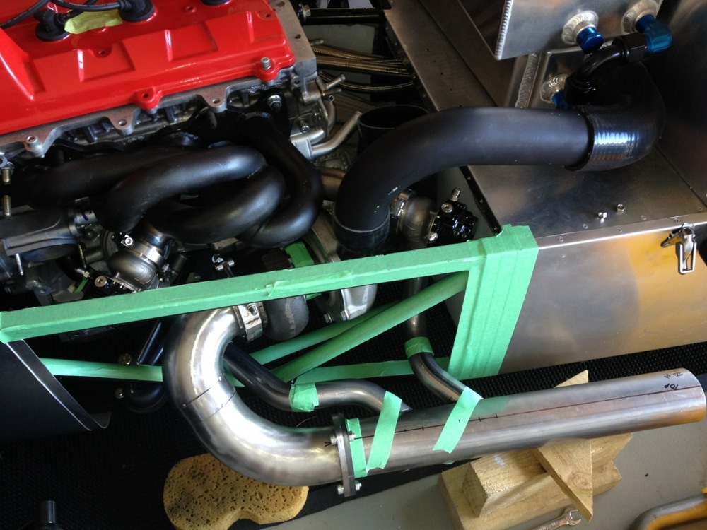
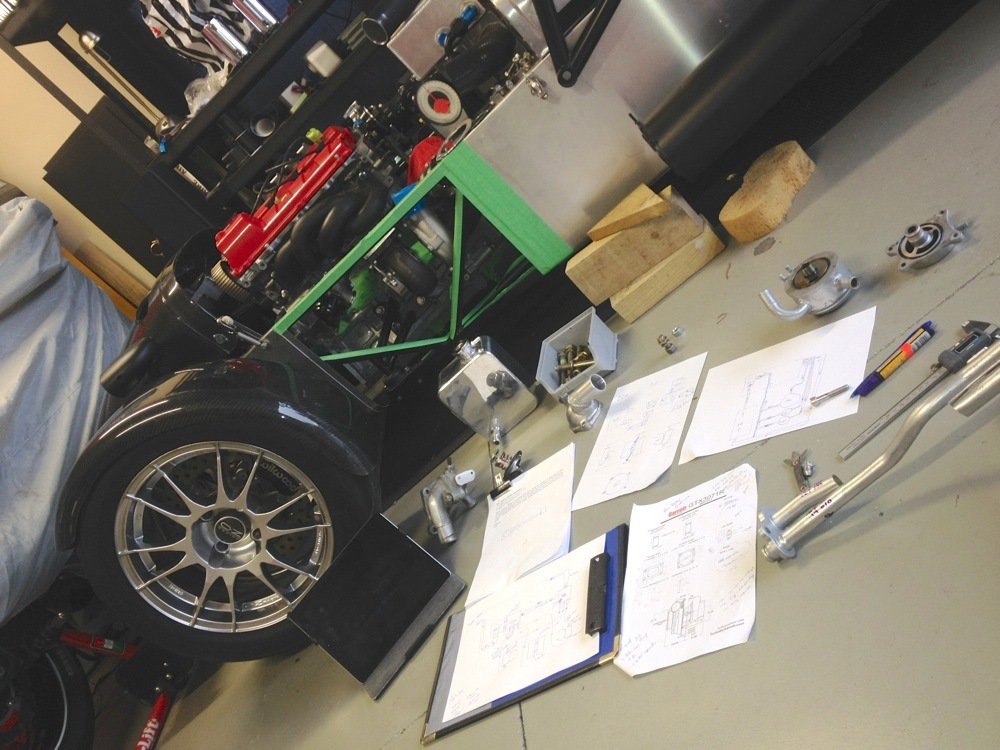
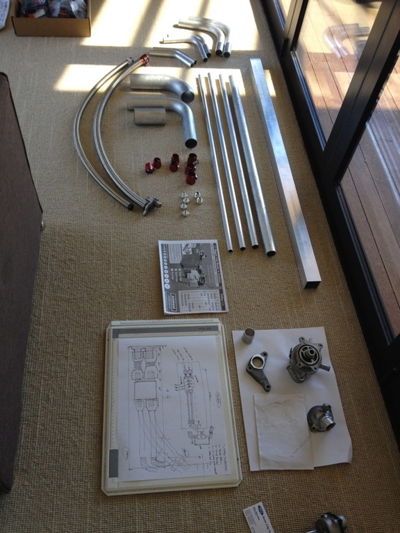
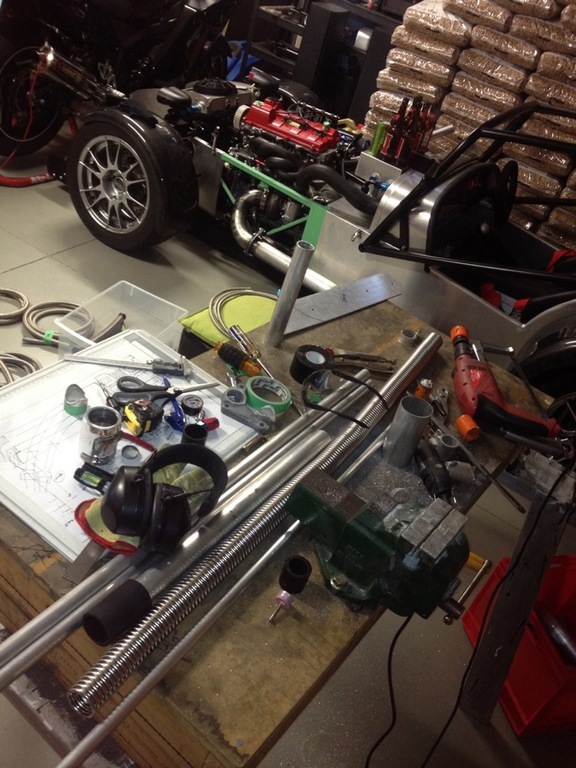
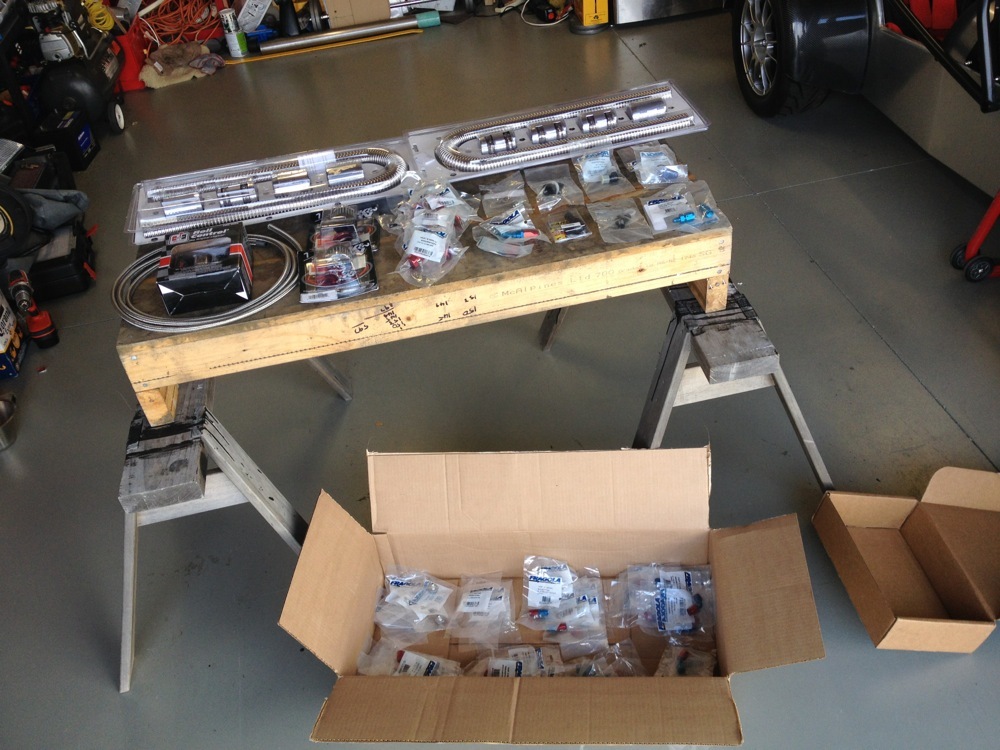
WATER, OIL, VACUUM LINES
A bit of time has been spent working out how to plumb all of the water, oil and vacuum lines around the motor. All of the original water plumbing had to be ditched due to space restrictions with the new Garrett turbo. I am having to design the whole system from scratch. I’ve worked it out in my head and am slowly fabricating/buying the individual components. A pair of pretty cool flexible stainless steel radiator hoses have arrived. There are three new water manifolds being made and a couple of blanking plates (removing the OEM block-mounted water-cooled oil-cooler etc). Major space restrictions at the rear of the head, so am having to be very clever in this area (4” air intake for the turbo, distributor cap air filter and water manifold all competing for limited space. Need to throw out the oval K&N and have another think about a different cool air box with a flat panel filter being fed by a top-of-bonnet scoop). The solid bypass lines have been replaced with s/s braided lines and just fit behind the turbo. Water lines to the turbo and waste gates have been solved but not made just yet. I have all of the hoses and fittings now, so just need to get back to them and start fitting the fittings. How fitting. ;-) Ditto the vacuum lines to the waste gates. Ditto the oil feed and return line to/from the turbo. This is a critical one as hose i/d and drop angles are all critical. The angle of the CHRA (middle assembly of the turbo between the compressor and turbine housings) is also critical and allow efficient thermal siphoning of the water feed and an unrestricted flow of the oil return to the dry sump. All a bit tricky. But, again, sorted. Done. Next!
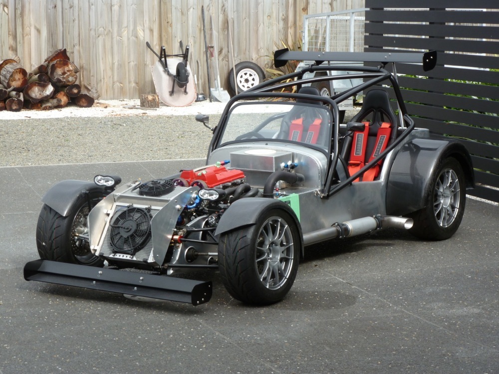
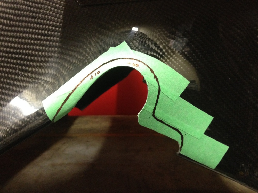
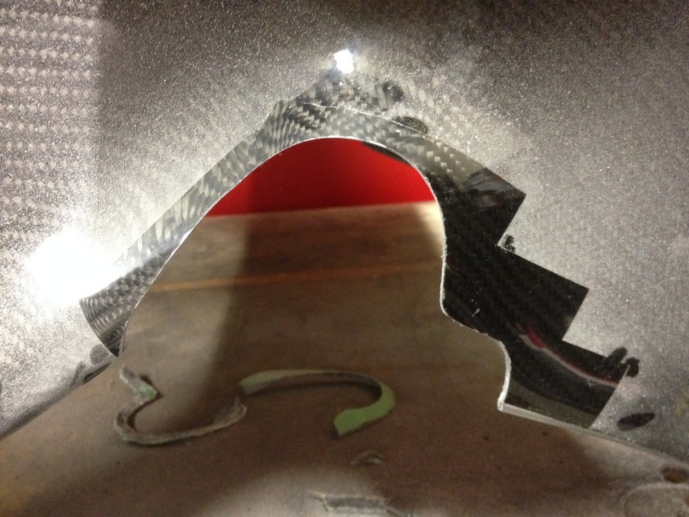
NOSE CONE, BONNET
Discovered a slight alignment issue with the new CF nose cone so had to get in there and trim away some of the cut-outs around the front suspension. Again, 4 beers before I start cutting CF. Messy, messy job. White dust everywhere. Scott is making me up a new bonnet with side louvers and a plain top surface so that I can cut out my own intake scoop and heat vent/intakes.
COLOUR SCHEME
Still sticking with the satin black vinyl wrap and stripes to match the Shoei XR1100 Tangents.
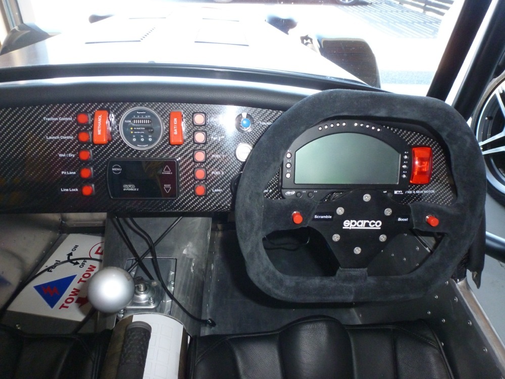
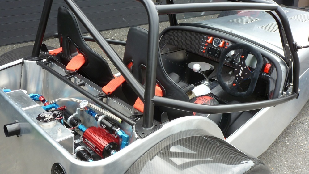
DASH
May have detailed this earlier, but the current dash is my third effort and I am now satisfied with the look and the layout. The only bummer now is that the GFB boost controller has gone and left a hole. I have also added a 2nd 9-position rotary switch (boost and traction control) so there is a wee bit of fiddling still to come here.
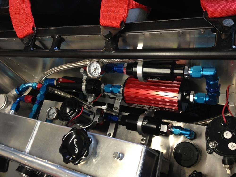
FUEL SYSTEM SUPPORTS
Almost finished the fuel system. Just a couple of return line fittings to fit. I have solved the mounting issue with the lift pump and filter but I am not happy with the workmanship of the supports, so will readdress this in due course.
LINE LOCK
Got a Hurst line lock for the front braking circuit, so burn outs will be a cinch! The Motec also can monitor brake line pressure so I need to source a pair of in-line pressure sensors. Add these to the long list...
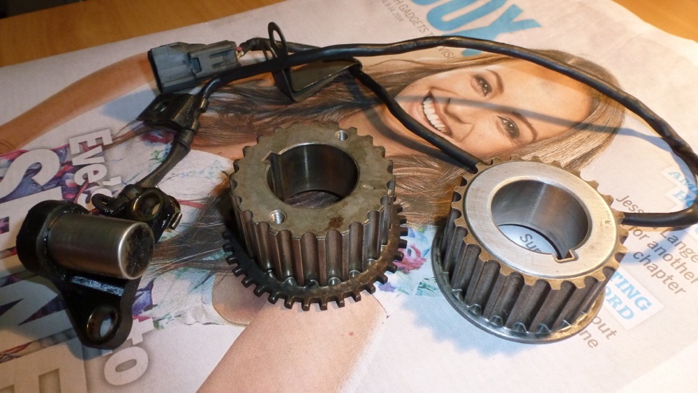
CRANK PULLEY CHOPPER WHEEL
The OEM Gen3 3S-GTE provides its crank and cam position data from mag sensors on the back of the cam-driven distributor. Apparently there can be as much as +/- 6 degrees of discrepancy in the timing due to the fact the the iron block and alloy head expand at different rates/high lift cams and strong springs can twist the cams (!) Eeek. 50hp losses on a 500hp motor with this setup. Eeek. Richard at MSEL recommended fitting a crank-based chopper wheel for the crank timing. Andrew Blank suggested a Gen4 crank pulley with inbuilt chopper wheel. Perfect. Another trip to the wreckers, $60 lighter and I am home with an oily sensor and new crank pulley. Plugged in the sensor to the loom, fitted the crank pulley to an electric drill and powered things up. Perfect signal. Cheers for the heads up, Andy.
L8R, Dudes. 8^)-
Gaz.