The Fraser Pit
2012 'Smoke'. 560hp 3S-GTE. - Timeline
Latest updates
The baton is passed from the crazy-man.... :)
Hi to those who are active on The Fraser Pit! I'm the enthusiastic noobie and this seems a great forum to capture data as the build continues. Also great source of ideas and inspiration as others have documented their builds.
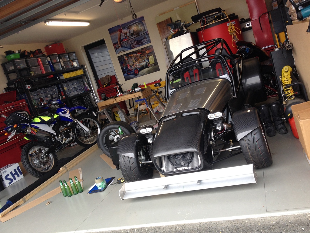
For those that may have seen this build earlier, I have taken on the metaphorical baton from Gazza to get this equally crazy machine on the road. I had always loved the Fraser 7 and aspired to own one one day, when I stumbled across 'Smoke' on Trade Me. I was excited by the vision of Gazza with his concept of approaching 1000hp / ton, and really was taken by his high quality product list. I jumped at the opportunity and became the proud owner of 'Smoke', which was in what I estimated as an 80% completed project - seems a gross under-estimate now.... On reflection, I also think 1000hp/ton is certainly worthy of some form of institutionalisation, so will be aiming for the more pedestrian 700hp/ton - what could go wrong!
Gazza started building 'Smoke' back in 2011, so it certainly had been one of those long-term projects. From what I can see, Gazza fell into the classic trap of project scope creep. He's done lots of things at least three times as the vision changed or evolved. Nonetheless I admired his vision to create one crazy machine.
So 'Smoke' was hauled up from Christchurch and now resides in Auckland, which is really handy as the Fraser factory is only 15 min away. Smoke has had its heart sent to GER for a once over to make sure all is good, as it was assembled at least 7 years ago... I'm in the middle of the wiring nightmare, which I'm sure a lot of Fraser build owners can relate to.
Anyway, that's probably enough for now. Will update the Parts page and then provide an update on the current status of 'Smoke'.
Steve
Hey
Morning, Team.
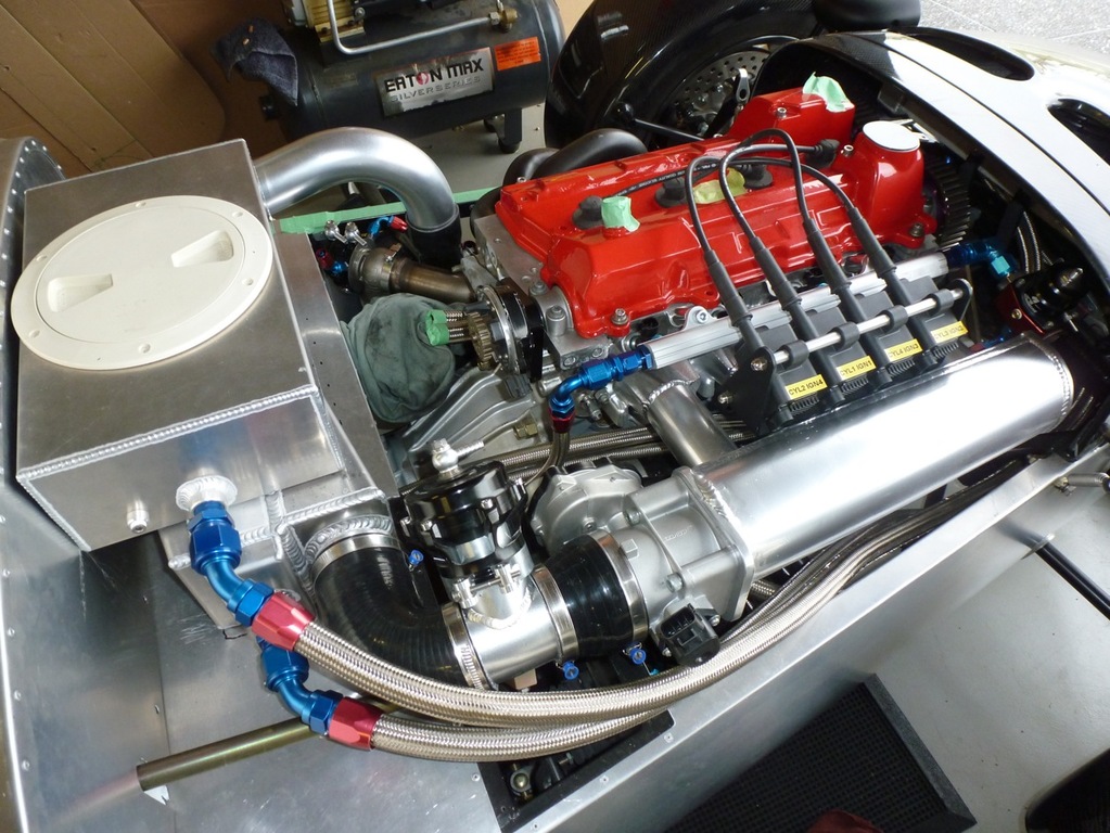
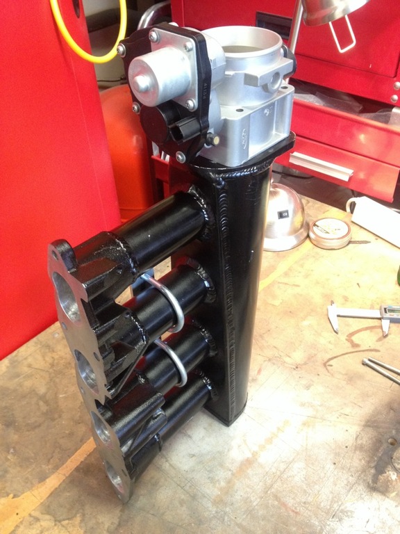
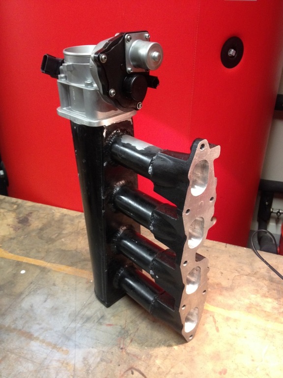
Some progress to report. Peterson scavenge pump filters fitted to the dry sump to save the pump from the inevitable grenading engine. Bit of a mission to run the lines above the 'speed-bump' height. E-Throttle Body mounting plate fab'd, welded to the intake manifold (Cheers, Dylan @ NZEFI) and painted. BOV link pipe shortened and a new silicone reducer fitted. Beautiful alloy Tilton throttle pedal removed (sniff) and the horrible plastic E-Throttle abomination from the folks at Ford takes it place. Still trying to work out how to mount it (maybe dinner and a movie first…). One saving grace with this upgrade is that I don't have to worry about a throttle cable!
"Too Infinity and Beyond!"
(Space Ranger rescued from the Metro. He was sitting on a pile of rubbish next to the grinder, looking up at me "Please rescue me, Mr, I don't wanna die! I am alive!". You've seen the movie. Had to jump into the pit (while no one was looking) and bring him home for a bath and some reassuring words). He thinks the Fraser is his spaceship and will return him to Sector 4 and Zurg. (...I haven't the heart to tell him).
L8R, Ladies and Germs.
8^)-
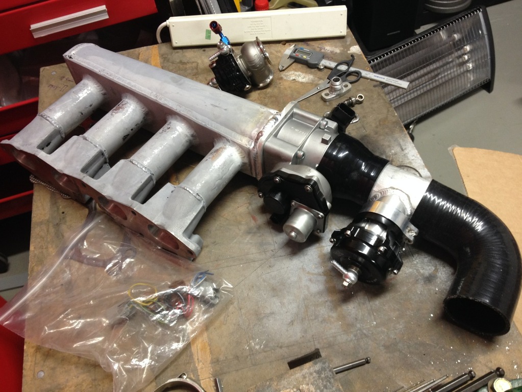
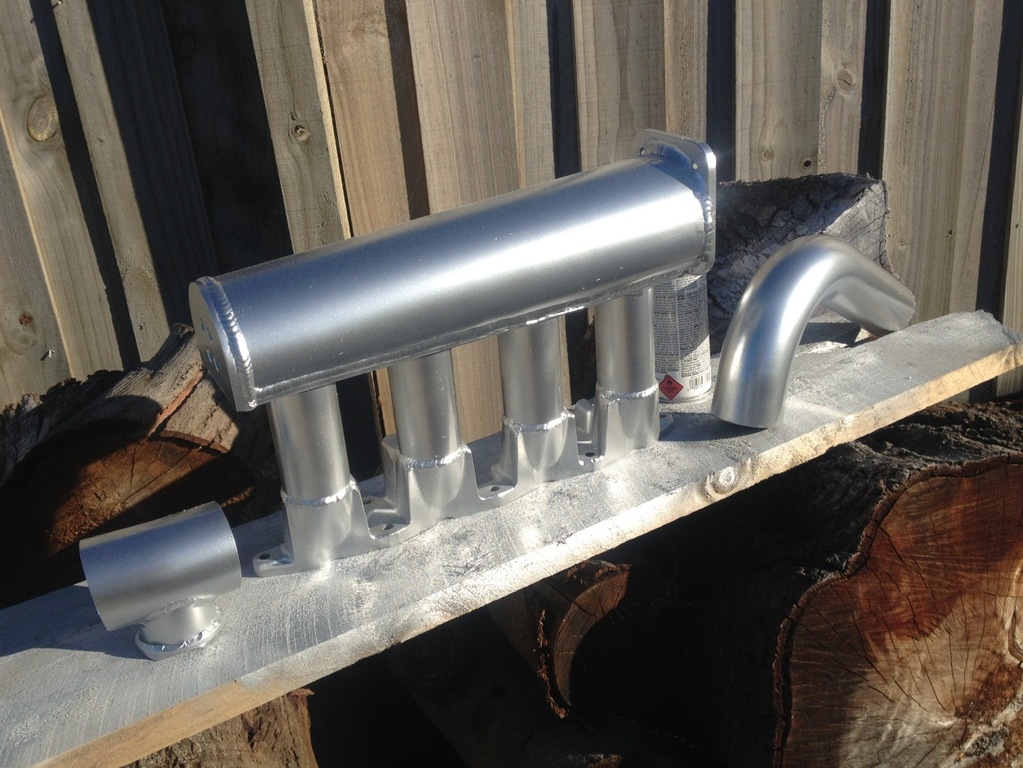
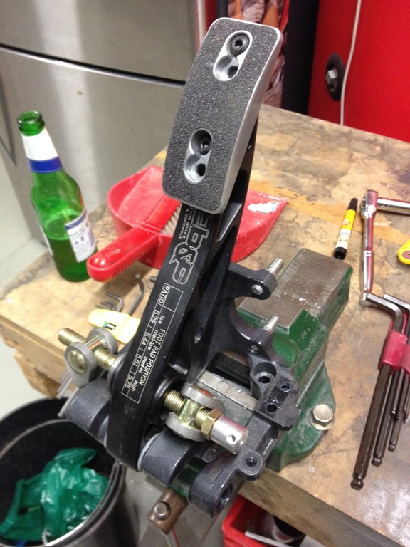
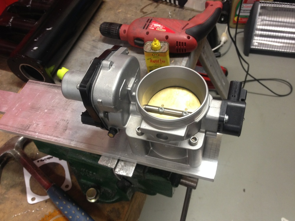
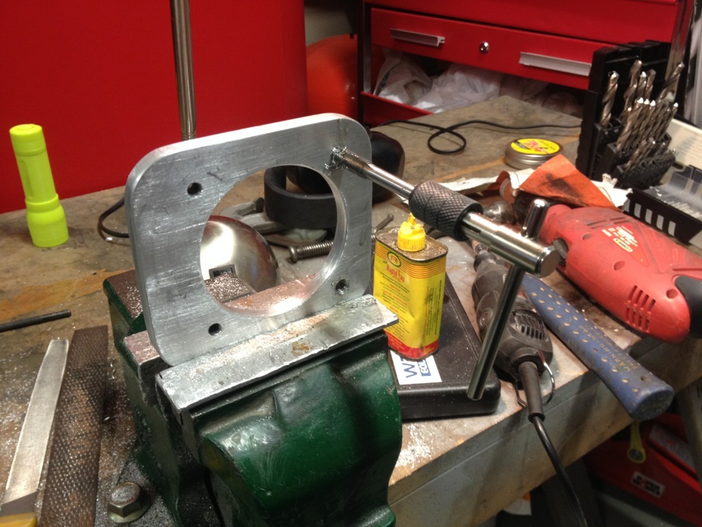
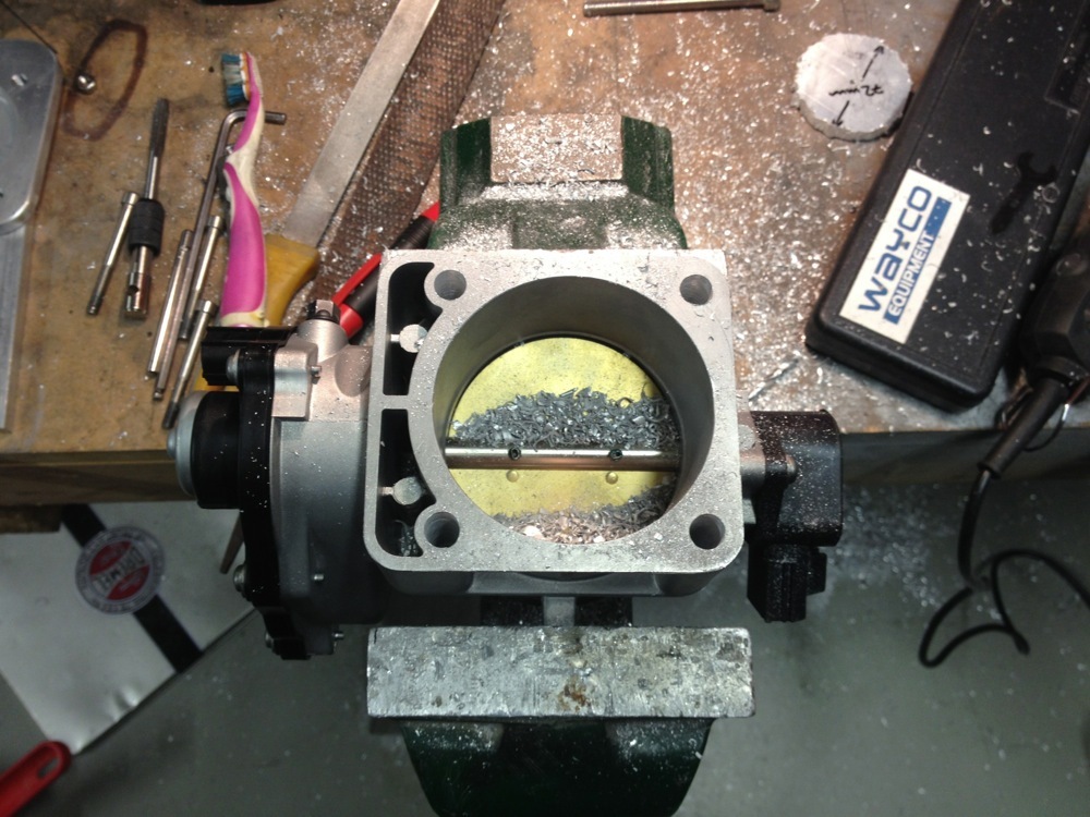
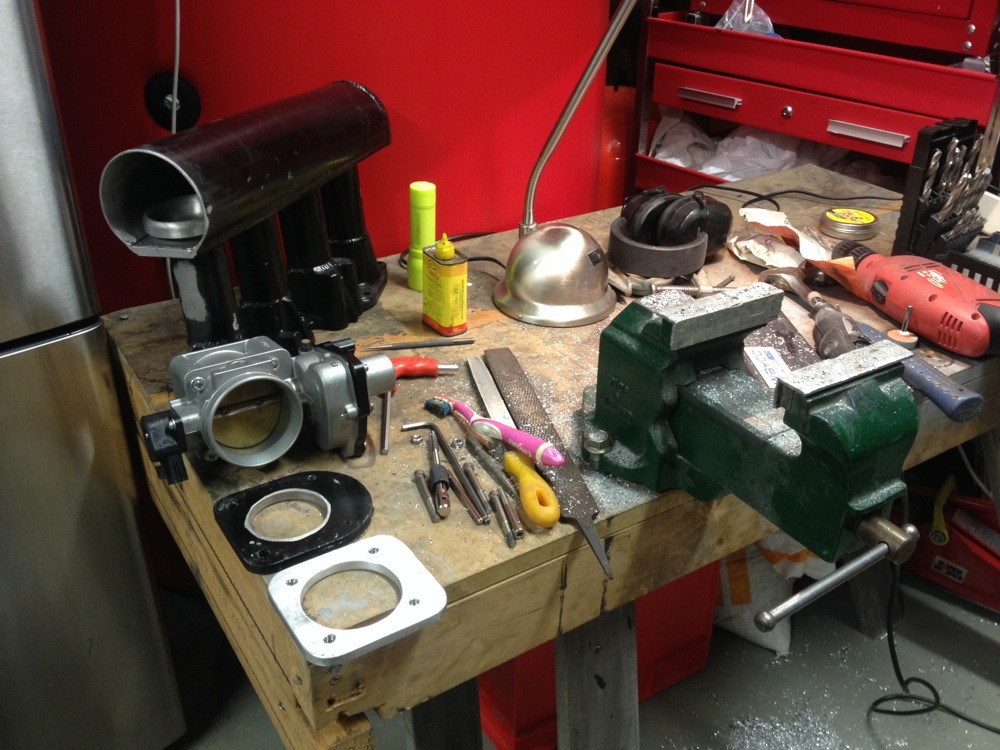
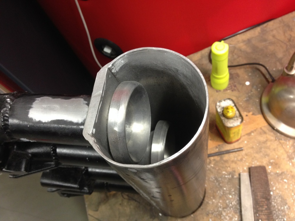
Throttle Body Mounting Plate
Hey.
Spent the better part of yesterday fabricating a new mounting plate for the E-Throttle Body and whizzing off the original plate from the intake manifold. 10mm ali plate, , measuring, scribing, grinding, linishing, dremmelling (is that a word?), sanding, drinking, 70mm hole, drilled and tapped M8x1.0 bolt holes. The strangest thing about the process, was that I got it right first time with no stressed-gibbon-like tossing around of aborted first or second attempts. What went wrong? ;-) I did screw up the original M6 mounting holes (long story), so was forced to take them out to M8 and nervously run an 8mm drill through the M6 holes in the throttle body. Eeeeek. Chewing of finger nails and furrowed brow.
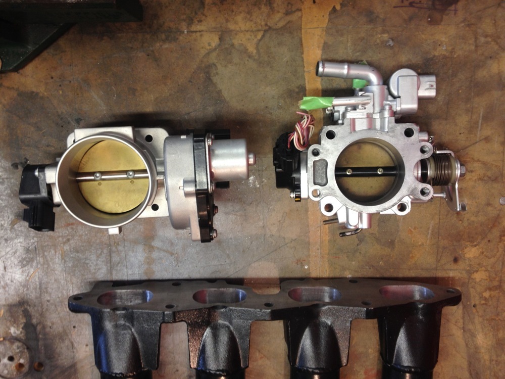
A bit of work to change over from the OEM TB, but this had to happen, despite the move to DBW, as the OEM TB was too small for the projected HP. 60mm plays 70mm i/d. Doesn't sound like much, but gives approx 30% bigger cross section.
Tuner Chaps reckon 70mm is good for 600hp. Good enough for me. But then the intercooler is 2.5" (63mm), so is this a restriction? Spearco rate this IC at 750hp, so obviously not. Stop over thinking things, Gaz.
8^)-
Hello, Strangers!
Well, apologies for the radio silence on updates. Get comfortable.
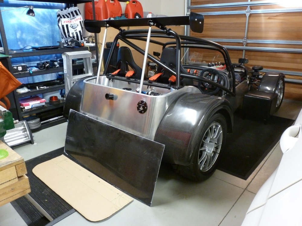
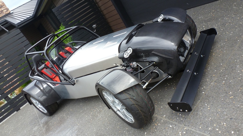
REAR WING
A pair of 1.5” PIAA spot-light roll-bar mounts and a pair of sprint-car front suspension struts along with a pair of very poorly (home) made wing cradles resulted in a moderately secure rear wing. I cut the end plates down in size to match the car’s tiny proportions then covered the wing in CF vinyl. Relatively pleased with the end result. Very hard to get the proportions/height/attack angle right when 7s don’t usually carry such hideous appendages.
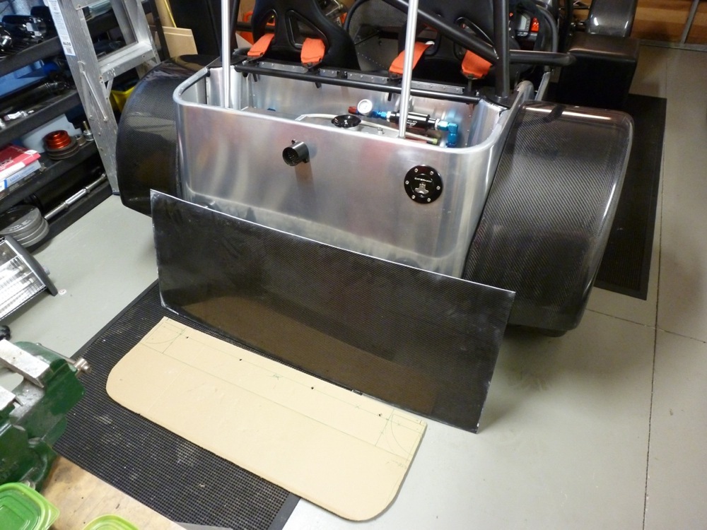
GLOVE BOX AND 'BOOT' LID
The last piece of fibre glass on the car has now been removed with the arrival of the CF glove-box. Everything is now either aluminum of CF. Nose cone with aero whiskers, front and rear guards, dash, seat bulkhead, glove-box and boot lid. I have a large panel of CF that I will cut down for the 2-piece boot lid. Probably have to fab a thin ali frame for the underside to give it a bit of strength. Looking around for a long piano-hinge to join the two pieces. Should look okay. Will also need to cut out slots for the wing struts. Carefully. I hate cutting into CF. Easier after 4 beers.
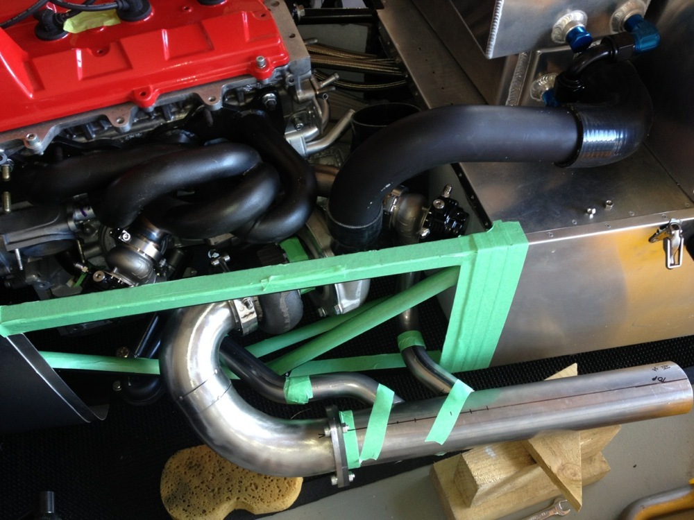
EXHAUST SYSTEM
After much swearing and throwing around of ruined pieces of steel tube, I managed to come up with a design for the waste gate dump tubes. A few trips between home and the welder’s shop, me producing ghastly tacks, them abusing my welding skills and seam welding things together in stages, home to test the fit, back to the shop etc. Came out pretty well in the end. Fairly discrete where they plug into the main 3” exhaust. Same can’t be said for the optional straight exhaust dump pipe and waste gate dump pipes. Just made these up for sh1ts and giggles post-certification. I can see a pending YouTube video of the engine running...HPC silver for all pipework most likely.
MOTEC M130 MAGNESIUM ECU WITH GPR SOFTWARE
Right. ECU upgrade. Again. 3rd ECU and the engine has not turned over once. After talking to a number of tuners about the project, I decided to upgrade to full Drive By Wire (Electronic Throttle, or E-Throttle). The DTA S80 did not support DBW so back it went to MSEL and an order was placed for the latest Motec M130 Magnesium with GPR software and Motec CAN-Bus Lambda kit. What a piece of kit. I am working through the very extensive Motec Webinars learing how to program and tune this beast. Very, very impressive piece of kit, must say. Have not blown it up (yet) so I must be doing something right (or just plain dumb luck...). With the arrival of the M130, my GFB Boost Controller and NGK Lambda Kit were both made redundant as the Motec controls everything now. Managed to sell these to a friend doing a home-built 7.
ECU WIRING LOOM
Wiring. Joy of joys. I love wiring. Not really. I took the original Link ECU loom, having modified it to suit the DTA ECU, and tore it apart again for the Motec configuration. Managed to produce a massive bird’s nest in the study, so mounted everything on a piece of MDF in the garage. Much better. I am adding ancillaries slowly and everything seems to be working okay. The coils and injectors are all plugged in, the AIM digital dash is talking to the ECU via CAN, the Lambda seems to be good, the crank and cam sensors are working (more on the crank sensor in a bit), and the traction control loom and sensors are also talking to the ECU. Working through the vast array of optional sensors/controllers that can be used and pairing these up with the variety of inputs/outputs on the Motec. Will place an order for sensors this week.
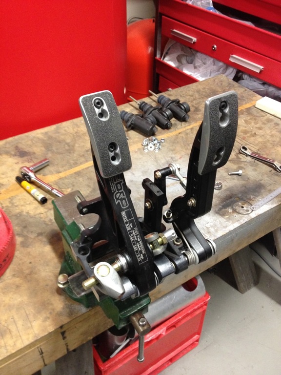
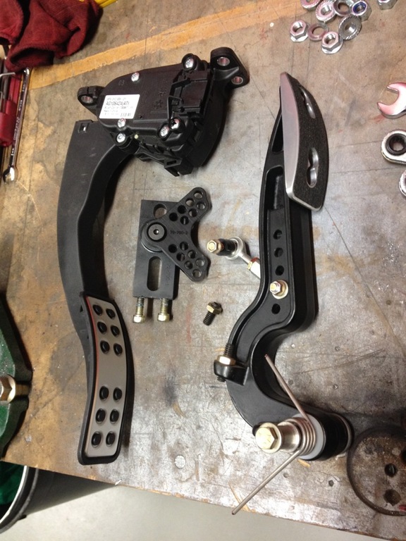
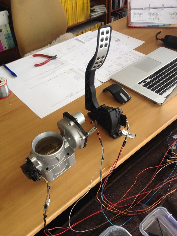
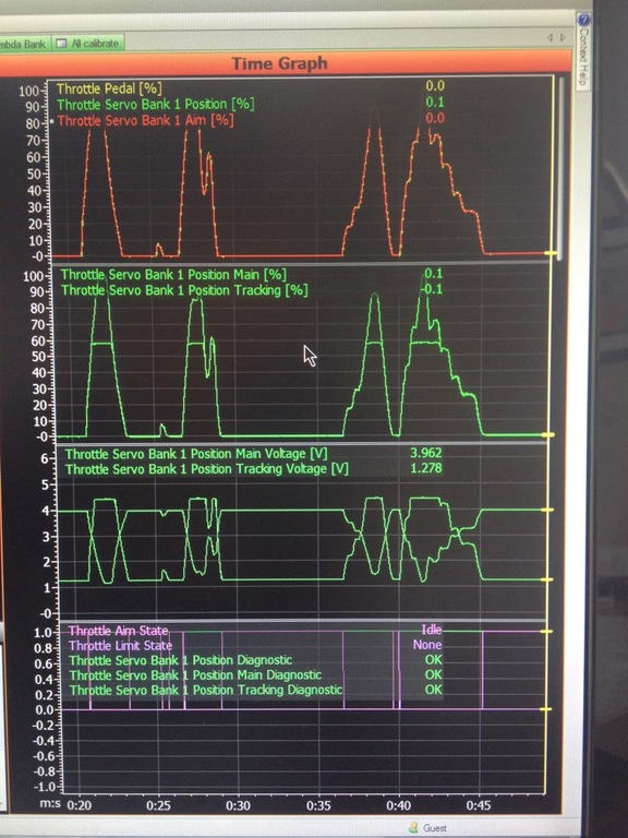
ELECTRONIC THROTTLE (DBW)
Right. This one is very cool. I sourced a new Falcon FG E-throttle pedal and Falcon BA E-throttle body from EBay Ausssie. Lots of phone calls and a lazy 20 over the service counter at the local Ford Stealership produced wiring diagrams. A day cutting myself to bits wandering around the wrecking yards produced a handful of OEM plugs to fit the pedal and throttle body. Several days of messing around with the programming of the ECU saw the throttle body operating perfectly. Very tricky to set up with the PID controller. I won’t bore you with details, but setting up the proportional, integral and differential gain, the various electronic clamps and offset and scale adjustments to prevent the throttle body jumping around like a landed fish was highly entertaining. Both the pedal and body have two TPS sensors that need to be set up and tuned. I set up two half-bridge outputs from the ECU to act as a full-bridge output to drive the servo motor on the throttle body. Tricky. Done. Sorted.
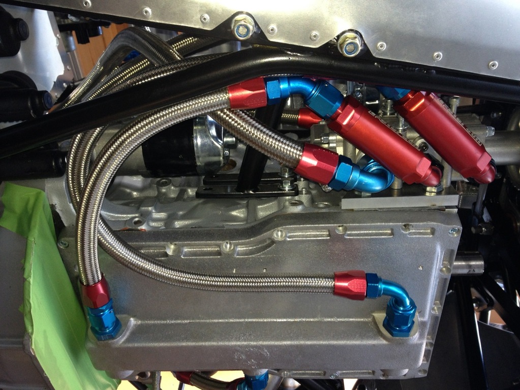
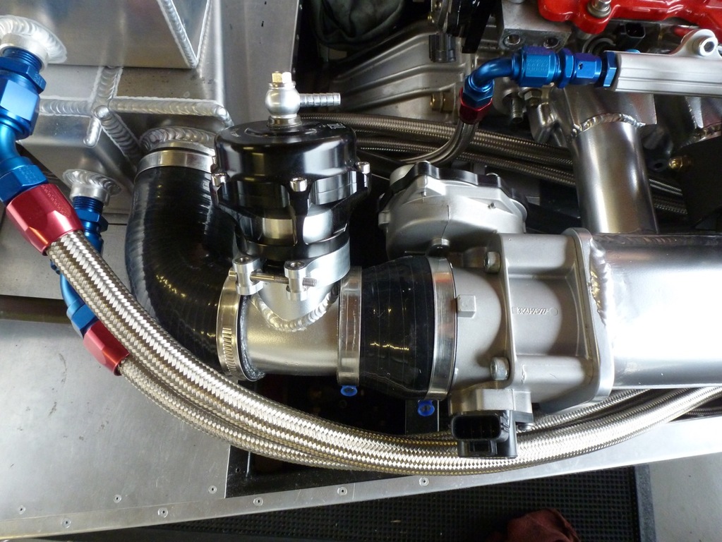
WATER, OIL, VACUUM LINES
A bit of time has been spent working out how to plumb all of the water, oil and vacuum lines around the motor. All of the original water plumbing had to be ditched due to space restrictions with the new Garrett turbo. I am having to design the whole system from scratch. I’ve worked it out in my head and am slowly fabricating/buying the individual components. A pair of pretty cool flexible stainless steel radiator hoses have arrived. There are three new water manifolds being made and a couple of blanking plates (removing the OEM block-mounted water-cooled oil-cooler etc). Major space restrictions at the rear of the head, so am having to be very clever in this area (4” air intake for the turbo, distributor cap air filter and water manifold all competing for limited space. Need to throw out the oval K&N and have another think about a different cool air box with a flat panel filter being fed by a top-of-bonnet scoop). The solid bypass lines have been replaced with s/s braided lines and just fit behind the turbo. Water lines to the turbo and waste gates have been solved but not made just yet. I have all of the hoses and fittings now, so just need to get back to them and start fitting the fittings. How fitting. ;-) Ditto the vacuum lines to the waste gates. Ditto the oil feed and return line to/from the turbo. This is a critical one as hose i/d and drop angles are all critical. The angle of the CHRA (middle assembly of the turbo between the compressor and turbine housings) is also critical and allow efficient thermal siphoning of the water feed and an unrestricted flow of the oil return to the dry sump. All a bit tricky. But, again, sorted. Done. Next!
NOSE CONE, BONNET
Discovered a slight alignment issue with the new CF nose cone so had to get in there and trim away some of the cut-outs around the front suspension. Again, 4 beers before I start cutting CF. Messy, messy job. White dust everywhere. Scott is making me up a new bonnet with side louvers and a plain top surface so that I can cut out my own intake scoop and heat vent/intakes.
COLOUR SCHEME
Still sticking with the satin black vinyl wrap and stripes to match the Shoei XR1100 Tangents.
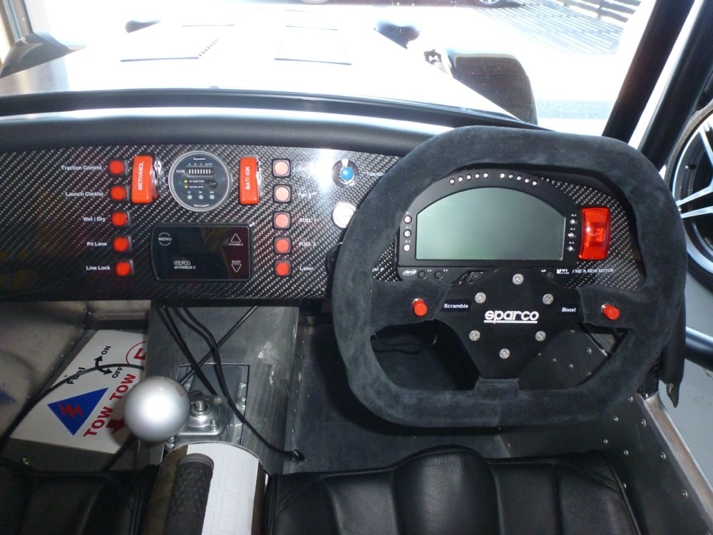
DASH
May have detailed this earlier, but the current dash is my third effort and I am now satisfied with the look and the layout. The only bummer now is that the GFB boost controller has gone and left a hole. I have also added a 2nd 9-position rotary switch (boost and traction control) so there is a wee bit of fiddling still to come here.
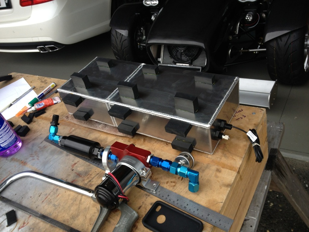
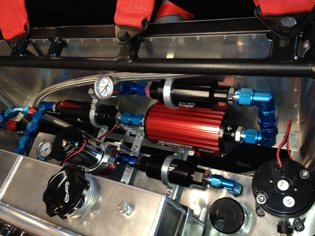
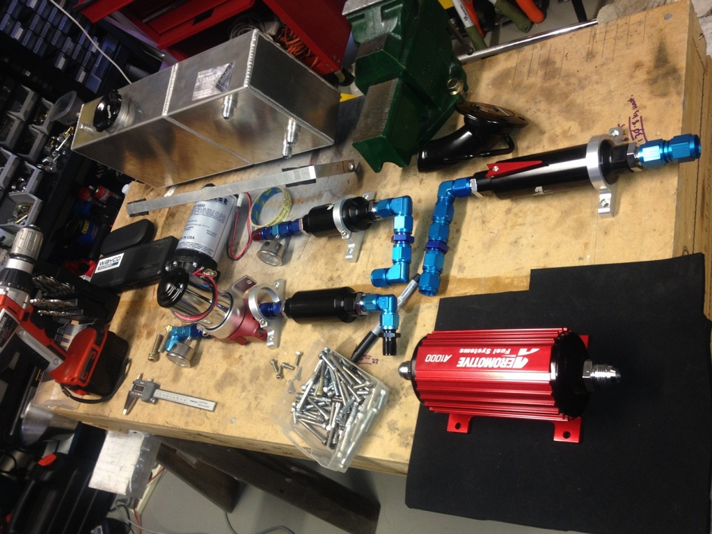
FUEL SYSTEM SUPPORTS
Almost finished the fuel system. Just a couple of return line fittings to fit. I have solved the mounting issue with the lift pump and filter but I am not happy with the workmanship of the supports, so will readdress this in due course.
LINE LOCK
Got a Hurst line lock for the front braking circuit, so burn outs will be a cinch! The Motec also can monitor brake line pressure so I need to source a pair of in-line pressure sensors. Add these to the long list...
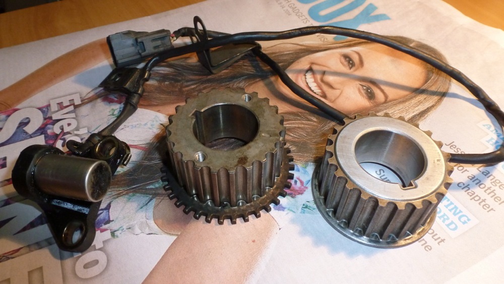
CRANK PULLEY CHOPPER WHEEL
The OEM Gen3 3S-GTE provides its crank and cam position data from mag sensors on the back of the cam-driven distributor. Apparently there can be as much as +/- 6 degrees of discrepancy in the timing due to the fact the the iron block and alloy head expand at different rates/high lift cams and strong springs can twist the cams (!) Eeek. 50hp losses on a 500hp motor with this setup. Eeek. Richard at MSEL recommended fitting a crank-based chopper wheel for the crank timing. Andrew Blank suggested a Gen4 crank pulley with inbuilt chopper wheel. Perfect. Another trip to the wreckers, $60 lighter and I am home with an oily sensor and new crank pulley. Plugged in the sensor to the loom, fitted the crank pulley to an electric drill and powered things up. Perfect signal. Cheers for the heads up, Andy.
L8R, Dudes. 8^)-
Gaz.

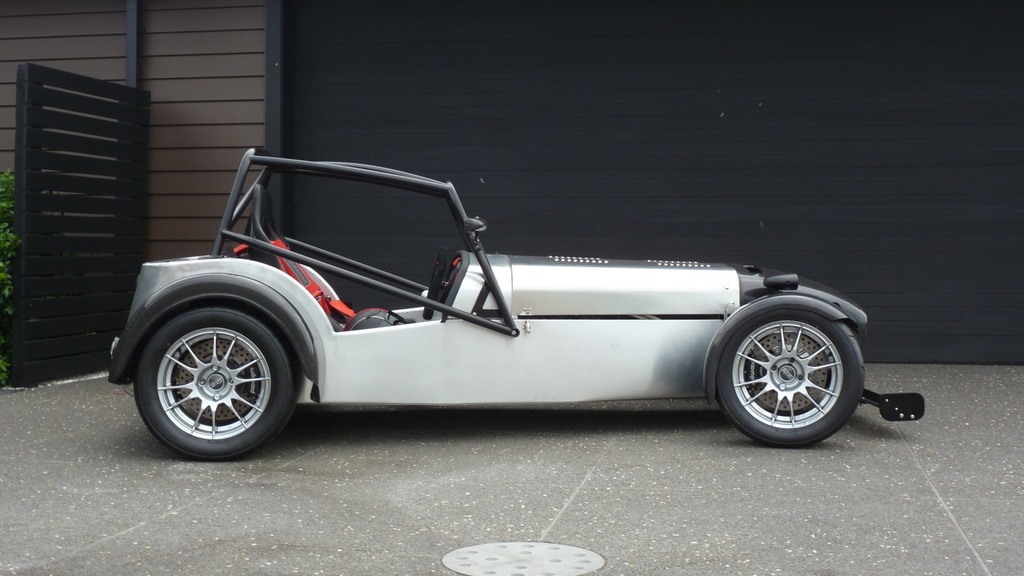
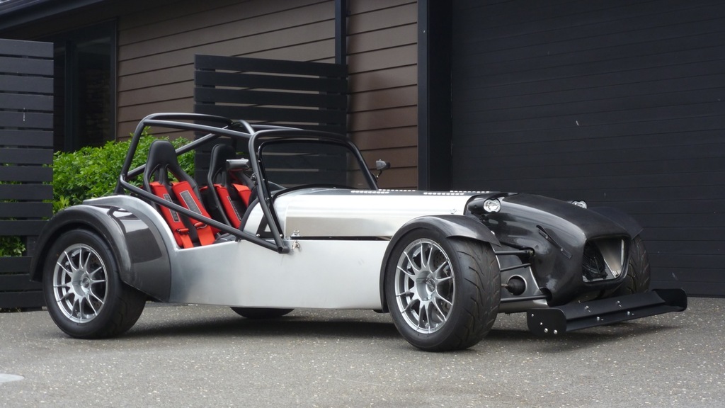
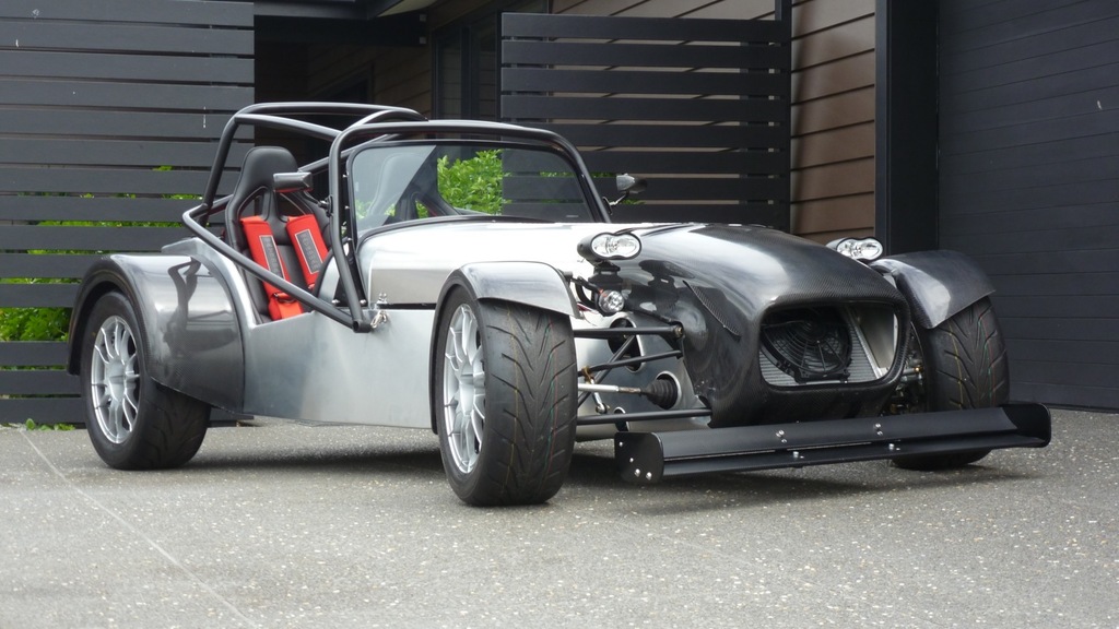
No Progress...
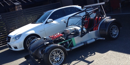
…to report, just been chopping up mild steel pipe and then depositing said pipe work into the rubbish bin as I attempt to fashion a new 3" dump pipe and 1.5" waste gate dump tubes. I am really a useless engineer…doesn't stop me trying though! Try, try, try again, blow up shit, burn holes, draw blood, then try again!
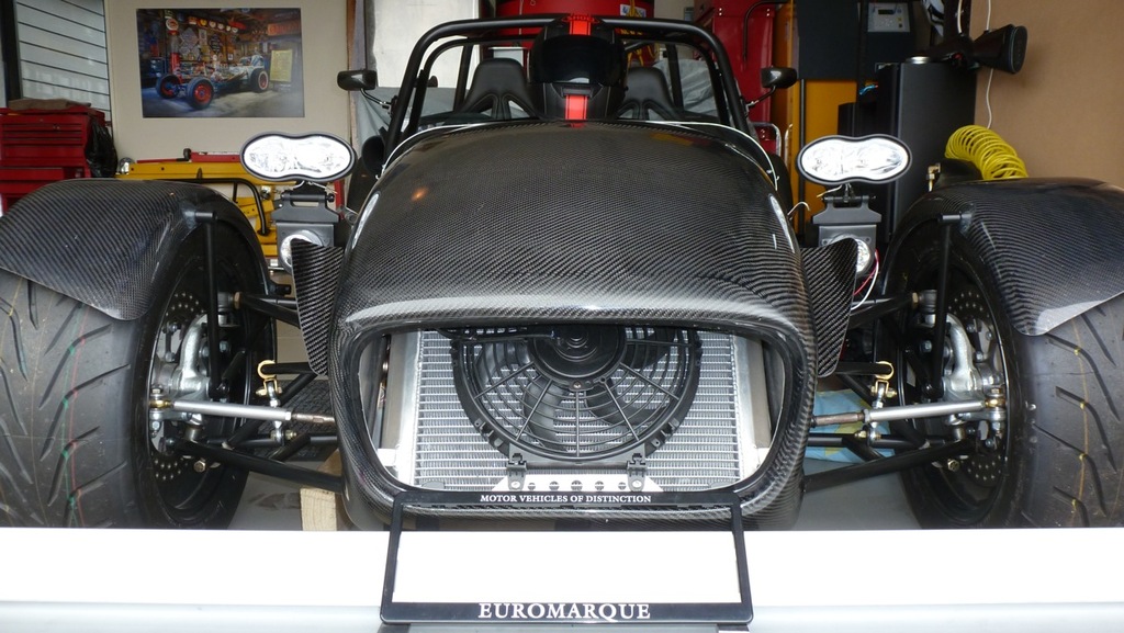
…so some gratuitous outside shots of Smoke in the meantime.
8^)-
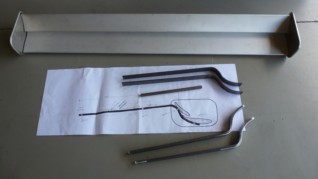
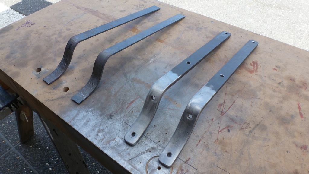
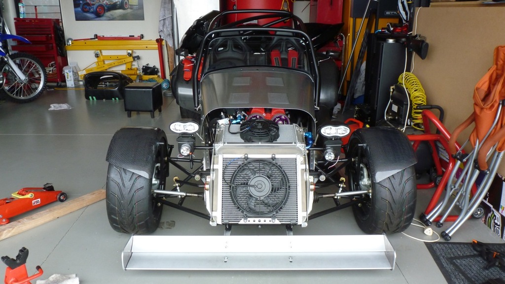
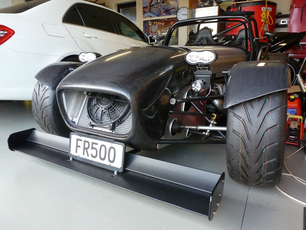
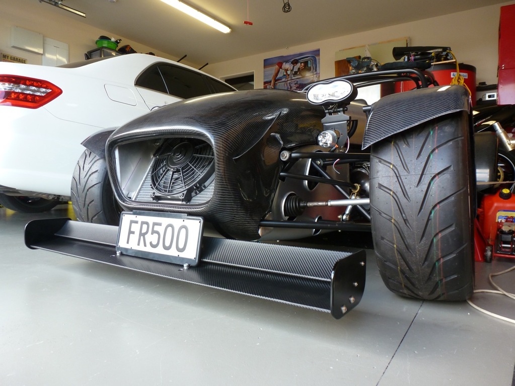
Front Wing
Well. Lordy. After months of me looking at the front wing and the front wing looking back at me, the silent impasse was broken. Narrowed the wing to 1200mm from 1350mm to bring it into proportion with the front of the car. Then went for a couple of 10mm x 30mm steel flat bar struts bolted to the chassis with x4 grade-12 M8 bolts. The thought of the wing detaching at 300kmph and slicing the front tires to shreds did not amuse me. Probably overkill (bad expression) but I stood on the stays (stayed on the stoods?) without the wing attached and they didn't bend. Hammered up a couple of 5mm flat bars initially with trusty hammer and vice (sorry Mr Vice and sorry neighbours...) to get roughly the right profile then asked the local engineer to bend up a pair of much nicer looking 10mm stays. Solid. The wings were drilled and an internal tube collar thingy fitted in the holes to prevent the wings being crushed when the nuts were tightened. The 2nd set of holes allows the wing to be moved into a more aggressive angle of attack. I'll fit discrete rubber bungs to the unused holes to tidy them up. Threw some CF vinyl wrap at the elements, some zinc galv black at the stays and a rattle can at the end plates (all very, very poorly executed, will get everything redone professionally near the end of the project, just want to check that I am on the rightish path with the colour scheme). Stole the FR500 plate off the Subaru (temporary lodgings) and looked at the car with its rego in place for the first time. Lump in throat (I coughed it up. Feeling much better, thank you). Will have a look at the rear wing tomorrow.
L8R, Ladies.
8^)-
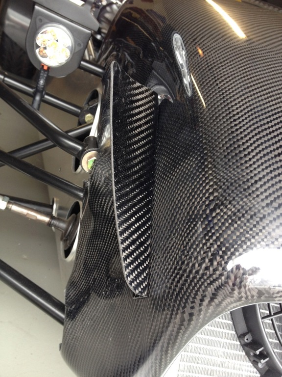
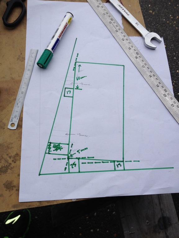
Aero Whiskers and Fuel System
Hey, Ya'll.
I have had a house full of young/loud/annoying nieces and nephews for the last 1.5 weeks so have spent a lot of time in the garage…I can report the installation of the Caterham aero whiskers and at long last a solution to the challenge of mounting all of the fuel system. What. A. Pain. In. The. Arse. Figured out how to position the twin-tank at exactly the right height, at exactly the right angle, at exactly the right distance from the rear body panel, so that everything fitted together and looked remotely parallel/straight/level. Scale drawing of the tank in-situ and rubber blocks cut to length and glued in exactly the right place. A bracket fab'd to hold it securely using the roll cage mounts. This one has been a freakin' brain-burner. Mostly sorted now, though. Bit of a pain drilling new holes in the installed tank and then having to suck all of the swarf out with mother's modified Dyson (shhhh, she doesn't know…) Clamping all of the braided s/s water/fuel/oil lines next and then I can terminate the fuel lines. Soooo much to do. Not thinking about it. Much.
L8R, Ladies.
8^)-
HNY, Team.
2014. Yar Hoo. Whoop whoop.
Hoping everyone has an excellent year.
Gaz and Tribe.